
wolfpaw
Administrators
-
Joined
-
Last visited
Everything posted by wolfpaw
-
-
 A variety of modular vines for RCT3. Created by n7.
 -
 A custom set containing bridge covers to use in RCT3. Created by Shadow.
 -
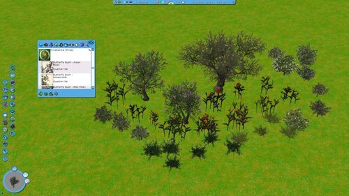 A variety of ornamental shrubs for RCT3. Created by n7.
 -
 A variety of ornamental trees for RCT3. Created by n7.
 -
-
 A custom scenery pack containing circus-themed items for RCT3.
 -
 A custom scenery set containing control room pieces for RCT3. Created by Ynor9.
 -
 A Disney-inspired Fantasyland set for RCT3. Created by Quinn.
 -
 A Super Mario 64 custom scenery pack for RCT3. Created by Nike.
 -
-
-
-
Haha, love the idea of Rock n Roller Coaster starring a bunch of different bands - great work!
-
Welcome to ParkCrafters! We have a section for RCT2 so we'd love to see what you do! Hope to see you around the community!
-
You charted RCT3 songs? Which songs did you chart and where can I get them!? I'd love to play my two favorite songs from RCT3, Savannah and Summer Air ?
-
This is a simple tutorial for creating effect points in Sketchup for use in RollerCoaster Tycoon 3. Written by Weber, 2012.


-
 This is an older outdated version of Sketchup that works with the plugins and importer for RollerCoaster Tycoon 3. Exact version is Sketchup 8.0.16846.
 -
This tutorial will show you how to make a custom firework launcher. First, you'll need the following materials so that we can get started: SketchUp 8 RCT3 Floor/Placements ASE Exporter You can find all of these materials in our downloads section. Let's get started! 1. Open SketchUp. For now, I am using SketchUp Pro 8. 2. When SketchUp Loads, Delete the Human. 3. Go to Plugins > RCT3 > Placement > Full Tile 4. Create a Box using the RECTANGLE TOOL. 5. Extrude it using Push/Pull tool 6. On the top of that Box, create 2 (two) circles/cylinders. 7. Extrude it again using Push/Pull tool. 8. Use the Text Tool (the one with ABC icon) Don't use 3D text! Make 2 (two) text in our mesh. 9. Name these text: fireworkstart01 and fireworkstart02 This will serve as our effect points. 10. Make an Arch on our mesh. 11. On the top of that Arch, use the Text tool (the one with ABC icon) Don't use the 3D text. Make again 2 (two) Text. This time, we will name it as fireworkend01 and fireworkend02. 12. Start deleting the Arch without deleting the two texts. 13. Start Texturing your mesh. Remember 64x64, 256x256, 512x512, and 1024x1024 pixels are allowed. 14. If you're done texturing your mesh, select your textures by using CTRL+Click, and don't select the black textures and the text first. 15. Right-click the selected textures (Highlighted in blue) and select MAKE GROUP 16. Right-click again. 17. Then select Entity Info. Notice a pop-up appears. 18. Note a pop-up appears; In that window, in the Name text box Name it Base 19. Click the White Box in the left corner of that window. Note a pop-up appears. 20. In that window, select your texture you've used! If you're done, Click OK and close the Entity info window 21. Select the two tubes/cylinder/circle/whatever and the Text also (Highlighted in picture) 22. Right Click it. Then select Make Group. 23. Note the box highlighted in blue 24. Right click again and select Entity Info. 25. Note a Pop-Up appears. 26. In the Name text box, Name it "Shooters" (Without quotation marks) 27. Select your textures by pressing CTRL or Shift 28. If you're done, click OK and the Entity Info window, too. 29. Select all first by pressing CTRL+A (Don't forget to remove/delete the Placement/Floor!) 30. Go to Plugins > ASE Exporter > Export 31. If this one appears, just ignore it by clicking OK 32. When this window appears, Give it a Unique name. 33. If you're finished, click SAVE. 34. When a message appears, ignore it by clicking OK. 35. You are done! For those who are having difficulty with this tutorial, please download the attachment below for an example file. Written by AzoRctMan. FWLauncher Example File.zip
.png.1a54a20d5bb7eaf1b3c38011b20ceb54.png)
.png.ae3cb30af35c51e8f33831b36cb415a0.png)
.png.34ead5b119d9e268b119089e32a0b712.png)
.png.1fcbe64760904646459f4359e8ceb840.png)
.png.5434e952944785bb74354b8767d40548.png)
.png.8ec148869ecc06fb3c5c66233879b2e3.png)
.png.dfa87163c1db500c761a8c9109ed0d79.png)
.png.50d1a13a8e60312620d569642d4f71a8.png)
.png.9992dfd1610ec40ff477b4406dec8e51.png)
.png.f2890de31ef65a7c9e11e98f6aa82395.png)
.png.eeab1e9a502266113f4b90bc55dc3c5d.png)
.png.92291f2d9581bff83d7fa9095247e8cf.png)
.png.0914e8ef8eb005feb347f6fb6a597c60.png)
.png.82cf127f454fe05d5cdd93bab826bd36.png)
.png.b4d938bcbfce2e43f481ca9d7efc0d96.png)
.png.97bbf01a00fee56a8fcc58020a546719.png)
.png.827e02d2459f304e1d3cdf4388875b87.png)
.png.12938e163a0e3c0a6f44e2efc7648f07.png)

-
This tutorial will show you various advanced techniques using the RCT3 Custom Scenery Importer. This document applies to the RCT3 Importer Version 16fix5. 1. Creating Simple Advanced Objects 1.1. Litter Bins Set Extra Parameters and Scenery Type to Litter Bin in the scenery settings. Set the Size Flag to Path Edge (Inner). Maybe Path Edge (Outer) works as well. 1.2. Loudspeakers Set Extra Parameters to Loudspeaker in the scenery settings. 1.3. Passport Machines Set Extra Parameters to Passport Post in the scenery settings. Set the Size Flag to Path Edge (Inner) or Path Edge (Outer). 1.4. Photo Spots Set Extra Parameters to Vista Point and Scenery Type to Photo Point in the scenery settings. Set the Size Flag to Path Edge (Inner) or Path Edge (Outer). 1.5. Objects that conform to the terrain There are two modes of conformance. 1.5.1. Full conform Scenery Type must be set to Flowers. As Size Flag I only tested Full Tile, but 1/4 Tile should also work. I have no idea how the latter actually works out if the object is bigger than the quarter tile though... Set Flag 13 and Flag 14. The model for the cover needs to be able to bend along both diagonals, so a simple plane out of two faces will not work. You need at least four faces with a vertex in the center of the model. Actually I didn't try that, my simplest model has 16 faces, a 2x2 version of what I described. Another disadvantage is that the engine is somewhat buggy with this, so sometimes you see the tile straight. This version does not work for terrain textured tiles. 1.5.2. Conform to one edge of the tile Scenery Type probably doesn't matter here (I used Small Scenery). Size Flag has to be Wall and the model has to be positioned accordingly. Set Flag 13 and Flag 14. The object is then placed like a in-game wall and conforms to the edge this “wall” is placed at. 2. Creating billboards and scrolling signs The creation of billboards and scrolling signs is very similar, so I'll discuss them simultaneously. 2.1. Creating the model The only thing you need to keep in mind when you create a model for a billboard or scrolling sign is that the part that shows the user image (billboards) or scrolling text (scrolling sign) needs to be a separate mesh. It can be a single plane, but more complicated meshes are also possible (eg. the round scrolling sign that comes with the game). 2.2. UV-Mapping That's where things get a bit tricky as RCT3 maps the image/scrolling text in a strange way. 2.2.1. Billboards You need to UV-map the mesh that will show the user image to the lower half of texture space upside-down. Do not overshoot. Here is a screen shot from Blender to show you how it's done (look at the coloured lines to get the orientation): 2.2.2. Scrolling Signs One full height of texture space is filled with the scrolling text, as billboards, upside-down. To prevent distortion you need to overshoot the mapping to the right, so it's width to height ration matches the mesh you apply it to. Here is a screen shot from Blender to show you how it's done: 2.3. Creating the OVLs Basically set everything up like for a normal scenery object. For billboards, select Billboard Texture as Texture Flags in the Mesh Settings window of the billboard mesh. You do not need to select a Texture or Texture Style for it. For scrolling signs, select Scrolling Sign as Texture Flags in the Mesh Settings window of the scrolling text mesh. In this case you need to select a Texture. It is shown in the preview when the user selects the sign in the menu. You can change the Texture Style, but other ones as the default SIOpaqueUnlit are untested. 2.4. Scenery Settings The best option is to load a billboard or scrolling sign SID from jonwil's collection on his page. You only need to set Extra Parameters to Sign for scrolling signs then. The basic setup for billboards is to set Flag 26 and to keep Extra Parameters at None. You don't need to set Flag 26 for generic stalls with billboards. The basic setup for scrolling signs is not fully tested, but at least you have to set Extra Parameters to Sign. If that doesn't work, try to set Scenery Type to Sign and Size Flag to Path Center or Path Edge (Join). 3. Working with Levels of Detail (LODs) We all want nice looking 3D models for RCT3 but we must remember that a lot of folks out there cannot use high detail models without lowering the performance of the game itself. It is now possible to use Level Of Detail (LOD) setting when importing your custom scenery into RCT3, a feature that will have thousands of RCT3 fans out there grateful for your hard work. 3.1. Definition First I'd like to explain a little about what LODs actually do and how to plan your model. LODs are simply a way of using multiple models for both different graphics settings and Draw Distances (DD). My computer's graphics card can handle some pretty complex 3D models, but other players' computers may not, so different LODs become very helpful for making happy graphics cards. LODs also have assignable Draw Distances. You can set how far away a particular version of your scenery is displayed. If I'm over at one side of the park and I have a high detail model on the other, there really is no need for the computer to try to draw the whole thing off in the distance, or draw it at all if it's a tiny object that really doesn't need to be seen that far away. Remember that RCT3 doesn't really know what your object is and it certainly can't decide to just drop certain faces in an attempt to reduce the detail levels (there are some rules it follows, but RCT3 still needs information to optimally work). You have to do that yourself- but don't worry! It's really easy! 3.2. Considerations about the model First lets think about the scenery item itself. For this tutorial, I'm going to use a sign with only two levels of detail. You can have more if you like, and I think three or four is probably more than enough for more complex items. If you were making a simple wall, there probably should only be just one level of Detail, but if that wall had a window, you might want to make several detail levels if, say, you had a fancy window frame. Lets look at the first, High Detail model: My sign is essentially a wall, with some extra pieces in the way of a frame and some decorations. Here I've made all the detail levels needed in one 3D file- I simply choose to import the meshes designed for the intended detail level. Note that I've named the meshes in my 3D file according to the detail level they represent: HD= High Detail level, LD= Low Detail level, and AD= Al Detail levels. For the High Detail version, I've chosen not to import the Low Detail Meshes and added HD to the end of the model name at the very top. Let's now look at the low detail version: Here you'll notice that I've simply chosen to not import the High Detail meshes and only import the Low Detail ones. What you don't see in either of the two images above are the actual mesh settings- In my High Detail meshes I've used a Gloss Reflection for the lamps, something that isn't needed for the low detail version for two reasons: 1- the low detail version is either going to be seen from far away or 2- the player's computer isn't very powerful and will be displaying the Low detail version, so why bog the computer down further if you don't have to. You will also notice that the name for this model in the top of the form has LD added to the end, to help identify it as a Low Detail model in the main Create OVL window. Again, remember that there is only one 3D model, I'm only changing what meshes to import for different detail levels. The model name at the top is used only by the importer and can be anything you want. 3.3. Setting up the LODs Lets now look at the two Detail Levels now set up and give them their Draw Distances: The Models list (top) shows the two unique Detail Levels of the model I'm using. Note that this piece of scenery has some Effect Points and I've only set them up on the High Detail version. This is because Effect Points affect the entire Scenery OVL, not the individual Detail Level versions. If you add a light Effect Point to the high detail version, it will appear for all other versions of this piece. The bottom window is where you assign the Draw Distances for each Level Of Detail version you have made. The numerical values are in the same Modeler Units that you may already be familiar with: a value of 4 would be the same as one RCT3 grid Square. So, in my examples here my High Detail version will be visible from 8 RCT3 grid squares away and the Low Detail version will be visible from 96 RCT3 grid squares away. What does that actually mean? Remember that you are making versions of your scenery piece at different Detail Levels to be shown based on what the player's Detail Level Settings (in their graphics settings menu) are set at. So what's going on with this Draw Distance setting? Well, each Detail level will be visible up to that distance away from the player's current position in the game: If their Detail levels are set low, then the Low version will draw from anywhere between 0 and (in my example) 96 RCT3 grid squares away. If the player has higher Detail Levels set, then the High detail model will be visible anywhere from 0 to 8 RCT3 grid squares away, and then the Low Detail version will then replace it from that point up to 96 RCT3 grid squares away. 3.4. New Observation The Draw Distance value entered, while it does affect how far away the model will be visible, it also decides where the detail level is on the Detail Level Slider in the Graphics Settings LOD menu. I just made a piece with 5 levels of detail, set at (High) 32, (Medium) 64, (Low) 128, Extra-Low) 192, and (Ultra-Low) 384. These values caused the detail levels to change only at one extreme end of the scale: in order to view the lower detail levels I had to slide the control all the way over to the left, until it wans nearly off. The values entered here might just be a subtraction from a fixed value- if you labeled the scale 4000 on the Left to 0 on the Right (values found in the Importer) then my model changes at intervals equal to these Draw Distance Values entered above on that scale. The last thing I want to point out is where the player's actual Point Of View originates from: If you start the Attract Sequence Editor (Ctrl-Shift-0) and place a camera (insert) and then back away, you will notice that the camera is about 1.5 RCT3 grid squares behind where you think you actually were. This offset needs to be considered into your Draw Distance settings: I always add a value of 8 to my intended Draw Distance, which adds 2 RCT3 grid squares to the viewing distance. Just something to remember. 3.5. Final Words Finally, in closing. So what distances should you use? Well, that depends on the size and type of the object. RCT3 will impose different Draw Distances based on what the player has set in their Graphics Settings, not just the Detail Levels. There are different Detail and Draw Distance settings for different types of scenery, too: A tree can have a whole different set of levels than the path items, which in turn could have different levels than rides, supports, shops, etcetera. Think about your object, how big or important it is when viewed from various distances, and then consider that the player's screen is only truly 2D in nature, and at some point any extra features that make your object 3D just cannot be drawn because there are only so many pixels the computer can actually use. A good example to look for are the heads of the peeps: at some point you will be too far away for the peep's ears to be drawn. If you were making a peep model, then you would make a detail level that does have some kind of simple ears (remember that Low Detail Levels are used on some computers when up close), but how complicated do they need to actually be? 4. Creating and using animated textures In this section you'll learn how to create animated textures. Before we start, please remember that animated textures are a completely different concept than animatronics (3D animated scenery, “true” animation). It is currently not possible to create the latter with the importer. Ride events are a special form of animatronics, therefore animated textures cannot be triggered/used by ride events. To create an animated texture you need to use the advanced texture edit window. Start by adding a texture to your object as normal but in the appearing file selection window do not select a file and press the Cancel button. If you did everything correctly, you'll get the advanced texture edit window. The following screen shot shows you how it will look after creating a simple animated texture: As of now, both lists and the Texture Name should be empty (Of course except for the “(Insert at start)” helper item). Before we continue, give your texture a name by entering into Texture Name. 4.1. Texture frames Texture animation is like a movie that plays on your object. Texture frames are the unique still frames this movie consists of. Unique means that if a certain frame should occur multiple times in your final animated texture, you need to add it only once. Repetitions are created in the animation sequence (see Section 12.2, “Animation sequence”). Now it's time to get to work and add some Texture Frames. Press the respective + button and select the first frame for your animation. You'll get the Edit Texture Frame window, which looks and works like a simpler form of the basic texture edit window. You can also select multiple files instead of just one. This will skip the Edit Texture Frame window and add the frames directly to the list . The list shows the index of a texture frame and the file name (without directory or extension). You will note that as soon as you add your second frame, the names will be shown in red. Red means that the respective frame is not used in the animation sequence, which at this point is normal as we haven't created the sequence yet. If you want to edit a texture frame, press the E button or double-click on the frame in the list . You can also change the order of the texture frames by moving them with the up/down arrows . 4.2. Animation sequence As stated above, the animation sequence defines the order of play of the texture frames. The Animation Sequence list shows the order top to bottom. Each entry in order shows the animation sequence index, how often the frame is repeated, the texture frame name and the texture frame index. Note that you cannot individually change the duration of a frame, you can only do that relatively by repeating it. Also keep in mind that texture animation is cyclic, so after the last entry in the animation sequence it restarts from the first. To add texture frames to the animation sequence, select them in the Texture Frames list and press the Animation Sequence + button . You can then reorder the sequence with the up/down arrows and change the repetition count with the left/right arrows . Note that if you add a texture frame directly before or after the same texture frame in the animation sequence, it will also be summed up into the repetition count. The delete button (-) deletes the complete entry in the list. The last thing you have to do is to choose the speed of animation. The Animation Framerate lets you set the speed roughly in frames (or rather animation sequence entries / repetition instances) per second. Now your animated texture is ready to use. Assignment to a model works exactly like for static textures, there is nothing you have to do differently in any other part of the import process. 4.3. Advanced topics This section explains a few things that are not absolutely necessary to know to create animated textures, but might come in handy, so I recommend to at least have a brief look. 4.3.1. Preview The preview helps you to prevent confusion on animated textures with lots of frames and/or complicated animation sequences. To show (or hide) the preview, press the Preview button . It does not provide you with a preview of the running animation, but shows you the texture frame you selected last in the Texture Frames list or the texture frame referenced by the last-clicked entry in the Animation Sequence list . 4.3.2. Freezing the animation sequence To understand this concept, you have to realize how the animation sequence is stored internally. Normally the editor gives you the impression that the sequence is stored by name (changing the order of texture frames doesn't influence the animation; if you delete a texture frame, all animation sequence entries that reference it are deleted as well). Internally the animation sequence is stored as texture frame indices (the number in parentheses at the end of each entry). If you change the texture frame order you'll note that these numbers change, indicating that the internal representation of the animation sequence changes (keeping the final animation constant). Freezing by pressing the F button will keep the internal representation constant. Before you tune out, I'll give you an example :-) The example animated texture in the screen shot gives a flip-flop animation from blue over green to red, then back over green to blue. Not let's assume that I want to exchange blue and green in the animation (green-blue-red-blue-green-...). To do that I would switch the position of blue and green at the start of the animation sequence, remove the green frame at the end and add a blue frame. Using freezing this can be accomplished quicker. First I freeze the animation sequence, then I switch the order of blue and green in the texture frames list and finally unfreeze the animation sequence - same result. It might not sound a lot quicker in this case, but this is a very simple animation, it can get much quicker in more complicated cases. All of this may still sound a bit complicated, so go on an experiment a bit with it, I'm sure you'll get the knack of it soon. A few things to keep in mind about freezing: As long as the animation sequence is frozen, you cannot edit it. If you remove a texture frame while the animation sequence is frozen, entries that reference it will be kept and some entries will now indicate that the frame they reference is gone. If you add a new texture frame, these references will become valid again (remember, reference is by index). If you unfreeze the sequence while it still has invalid entries, they will be removed. 5. Credits Atari® and Roller Coaster Tycoon 3® are trademarks of Atari Inc. All Rights Reserved. Written by Belgabor and Vodhin


-
-
Awesome, thanks so much! This will be extremely helpful for anyone that still does projects in RCT3. When you recorded it at 1/4th speed and sped it up did you notice any lost frames from the game? I'm curious if this process will also work for pyro shows where you have to have the video synced to the audio perfectly.
-
This tutorial will lead you through the steps required to import your first object into Roller Coaster Tycoon 3®. Only the options and steps required for a basic import will be explained, do not expect to hear about everything you can do with it. This also means that all of these steps are required! This document applies to the RCT3 Importer Version 17fix3. 1. Preparing for the Import This section will show you what you need to do before running the importer. 1.1. Initial preparation While it may sound trivial, it's an important step to keep things organized: Create a directory on your hard disk that will hold your custom scenery sets. You should also create a subdirectory within for each set. Within each of those it is recommended to put each Custom Scenery (CS) object along with all belonging files into it's own subdirectory. 1.2. Creating the 3D model This process is very much beyond the scope of this document. You need to get a suitable 3D modeller and read a few tutorials on how to use it. Here is a list of the modellers used most often for creating custom scenery for RCT3: 3DStudio / 3DSmax. Very expensive professional 3D modeller. If you can get an academic license you might be able to afford it. MilkShape. Cheap (25$) shareware with a 30 day trial period. Was the custom scenery creation tool of choice for a long time, but more and more try their hands on Blender. Free open source professional modeller. It's user interface is pretty non-standard and therefore requires a bit of patience to get used to. When you get acquainted to it you won't want to miss it anymore and Blender becomes a very powerful tool. SketchUp. Comes in two versions, Google SketchUp (free) and SketchUp Pro (commercial, trial available). Very easy and intuitive to use. Current drawbacks are that it tends to create too many faces on round objects which can be hard to fix later. Another drawback is that SketchUp sometimes produces superfluous faces and edges which have to be cleaned up in an other modeller (more on faces below). A script to export directly from SketchUp to ASE can be found on our downloads page. For more detailed information and links to less commonly used modellers as well as modeller specific tutorials see our downloads section. For creating your models, you should keep the following guidelines in mind: Keep your first model simple to get accustomed to the importing process. A simple cube works well for example. Make your model the right size and position it correctly. A RCT3 square is usually 4x4 of your modellers units big (in SketchUp things are a bit more complex). Keep the number of faces as low as possible. A face (also called “poly”, “tri” or “triangle”) is the smallest surface subunit of a model and the unit that causes “work” for the 3D engine of RCT3. Therefore the more faces your model has, the longer the engine needs to display your scenery item which may lead to lag. As a rule of thumb try to stay below 500 faces, even better below 300. Note that the engine uses triangular faces while most modern modellers can use at least quads (faces with four corners or vertices). These are converted to triangles in the export or conversion process, so the actual number of faces may be a lot higher than your modeller shows. Some tips on how to keep your face number low: Make things only as round as necessary. Rounded parts usually use the most faces. As a rule of thumb never give a full circle more than 16 sections without good reason. If the part of the object is really thin, you might even get a good looking result with just three sections and keeping it welded (more on that below). The same applies to spheres. If possible use low iteration icospheres. Modellers can also create so-called uv-spheres. These use up more faces but are easier to uv-map (hence the name. More on uv-mapping below), so use them only if you need a complex texture on it. Remove unnecessary invisible faces. If your model has invisible (inside) face1.3s due to the modelling process, remove them as they will use up processing power. Keep in mind that they may still affect lighting if their vertices are welded to visible faces, so it may be necessary to keep them in some cases (more on this below). Consider using alpha textures. This is a rather advanced topic, but you should be aware of the possibility. If you want to create an object with a filigree see-through pattern (a railing or iron works for example), it may be easier for you and on the engine if you don't model the pattern but rather use a plane that has a see-through (alpha) texture assigned. Selectively weld/unweld your model. To understand this topic you first have to understand how the RCT3 3D engine (and probably all other 3D engines as well) calculates the lighting of the object. For this the difference of the direction the light falls in (in RCT3 the sun at day and lamps at night) and the direction of your objects' normals is used. Now you may ask what a normal is. Let's start with a face normal. You can imagine this as an arrow that points away form the face being perpendicular to it, so if compared to the direction the light comes in you get the angle under which it hits the face and it is possible to shade it accordingly. To make objects look more realistic, the 3D engine rather uses vertex normals. This concept is a bit harder to understand. The vertex normal is a property of the vertices (corners) of your object and represent the normal of the tangent plane of your object at that vertex. To understand what that means imagine your object as a real and put it on the top of your desk touching it only with one vertex. That (roughly) makes your desk the tangent plane of that vertex, so it's normal would point vertically to the floor in that position. Vertex normals are automatically calculated by your 3D modeller, usually as the mean of the face normals of all faces the vertex is part of. Here comes the concept of welded and unwelded vertices into play. Imagine the corner of a cube. Usually your modeller creates it welded. This means the corner is only one vertex which is used by the three faces that border it. If you unweld this vertex (How to do that depends on your modeller, search for Unweld or Unbind points/vertices) a copy of it is created for each face that uses it. In the example above the one corner vertex is replaced by three, one for (and used by) each face. If you think a bit about it you will realize what that means for the vertex normal(s). If the vertex is welded, its vertex normal will point away from the center of the cube and the engine of RCT3 will treat it as if the object was supposed to be round there. If the vertex is unwelded, each of the three vertices in it's place gets its own vertex normal. As each is only part of one face, its vertex normal is identical to the face normal. The take home message is you need to unweld vertices/edges if they are supposed to look “pointy”, if they are supposed to be round, keep them welded. Usually you cannot selectively unweld a vertex in regard to certain edges, you can only fully unweld it. If you want to keep some edges that it's part of welded, you need to first unweld it and then weld the vertices of the faces whose common edge you want to have welded. Note: How to weld depends again on your modeller, it can be a bit hard to find (for example it is called Remove Doubles in Blender). Recent versions of Blender have the EdgeSplit modifier which makes this very easy. Usually you shouldn't bother using the 3D modeller's materials for your object. RCT3 and therefore the Importer can only used uv-mapped bitmap textures, while most modellers use procedural (calculated) textures. There are ways to make a bitmap texture form such procedural textures (usually called texture-baking or uv-baking), but usually they don't lead to a satisfactory result. 1.3. Obtaining a bitmap texture for your model As stated above you need to use bitmap textures for your custom scenery 3D models. A further prerequisite for the final texture you'll use in the importer is that it has to be square and its width and height have to be a power of two (for example 64x64, 128x128 or 256x256). Note that this size can have an effect on the objects load time and the amount of memory needed later in the game leading to lag, so don't make them bigger than necessary. I'd recommend to use 256x256. If you have a very detailed texture you could use 512x512. If your object is single-colored, even a 4x4 texture is enough (maybe even 1x1 works, but I haven't tested that). The first (and hardest) option to obtain a texture is to draw it yourself using a bitmap editor like Adobe Photoshop or The Gimp. Even if you don't want to draw your own texture it is a good idea to have a bitmap editor around to resize or manipulate them. The second option is to find a suitable texture on the net. There are lots of free (and even more non-free) texture sites out there. One thing you should keep in mind is not to violate copyright. It is not necessary to say something is protected by copyright, copyright is automatic! So if a site doesn't explicitly say you are free to use images or textures on it, you may not. Also remember that symbols and brand names can be protected by copyright or trademark laws, so it's better not to use them. If you're annoyed by this, remember it protects you as well. So whatever CS you create, others may not host the set or rip your models or textures without your permission =) A third possibility is to use a special texture creation software. A good (and free) example is Wood Workshop by Spiral Graphics, which is a tuned-down version of their commercial texture creator, Genetica. They also offer free texture packs which can be used with the Genetica Viewer (also free). There are also other texture creation software packages, just Google for them (and tell me if you find a good free one :-P ). In whatever way you get your texture, it is always good to get a seamless one. A seamless texture is a texture that doesn't have a visible rim if tiled (checkerboarded). This allows you a bit of sloppiness when uv-mapping or getting a more detailed looking model with a smaller actual texture size. You also should create an icon texture at this point. This is a bitmap that will hold menu icons for your theme. It has the same restrictions as a model texture, the only thing that is different is that you can (and should) use a PNG with transparency here, otherwise the alternating white/gray background will not show through. The standard size is 512x512 and usually 64x64 icons are set up. You don't need to create the final icons at this point, but at least a temporary icon texture is needed. Icons are later numbered starting at the top left, going right first and then down (like western writing). 1.4. UV-Mapping UV-Mapping is used to “assign” a (bitmap) texture to a model and is done inside your 3D modeller. I put “assign” in quotes since technically it's not correct. What you do is give the vertices of your model an additional set of coordinates (additional to its spacial x/y/z 3D coordinates) in so-called texture-space. These coordinates are called “u” and “v” (hence uv-mapping) or “s” and “t”. There is a difference between these two naming conventions but that doesn't need to concern you for creating custom scenery. You also should know that these coordinates are relative. That means 0 represents one end of the texture and 1 the other one, so the size of the texture you use for uv-mapping can differ from the one you use later in the importer, only the layout of the texture has to match (ie. don't mirror it). While this may sound complicated or strange, it just tells the model (and later the 3D engine) which part of the texture to use for which part (face) of your object. So what you should remember from the explanation in the previous paragraph is: The uv-mapping is a property of your model and is therefore stored inside the 3D model file. You don't have to assign the same texture to the model in the importer that you used to uv-map. This also applies to the size. (Note for later: You always have to assign a texture in the importer, even if it's the same one you used to uv-map. The information which texture was used is not transferred to the importer.) As above for creating the model, here is a list of things to keep in mind about uv-mapping: The exact process depends on your 3D modeller. Usually there are specific tutorials about uv-mapping for it. Depending on the complexity of your model and texture, uv-mapping can be a very time-consuming process that can take you as long or even longer than creating your model. UV-map as exact as possible. Small errors can be very visible and annoying in your finished object. The texture is tiled in texture space, so if you map over the rim of it, it starts again from the opposing side. This will lead to a visible seam if your texture isn't seamless. If you need more than one basic texture for your object, you can put them all into one texture bitmap and uv-map the parts of your model to the correct part of your texture. This is common practice. 1.5. Coordinate system As long as you are still in your 3D modeller you should take note which coordinate system it uses. We need two properties, which axis points up and its handedness. The first is easy, just have a look whether the x, y or z axis points up. The second is a bit more tricky. A coordinate system can be left or right-handed. Here is how to determine the handedness: In most cases you get a right-handed coordinate system. 1.6. Converting the model The importer only supports loading ASE and MS3D files at the moment. If you can directly save or export to one of these formats, do so and skip this section. If not, you need to convert your model to ASE. The free converter of choice is Biturn. Get it and convert you model to ASE (3ds max ASCII) format. It's not recommended to convert to MS3D format as Biturn is known to do strange coordinate system conversions when converting from MS3D, no one knows what it will do if you convert to MS3D. 1.7. Getting and installing the importer Maybe you already did this, if not, get the importer form our downloads section. It is distributed as a ZIP file, put the contents into a directory of your choice. Updates should go into the same directory as some settings are stored inside a small file in this directory. Always make sure you overwrite all files when you update. 1.8. A few notes on OVL files The OVL file format has been designed for RCT3 by Frontier. You don't have to know everything about their internals, but there are a few things you have to know: You may not change the name of an OVL file in the Windows Explorer. If you want to change the name you need to recreate it (see Section 2.2.4, “Save and Create”). You may not change the name of any directory of your installed theme. If you want to change them you need to change the respective setting in the importer and reinstall. If you changed any file or directory name you have to delete any previously installed old version of your theme from Style/Themed (see Section 2.4, “Save and install the theme”). 2. Importing Your First Object At this point you should have installed the importer and prepared all necessary files (model, texture bitmap and icon bitmap). 2.1. Primary setup After starting the importer you'll see the main window of the importer: Figure 1. RCT3 Custom Scenery Importer, Main Window The first thing you should decide is which theme type you want to give your set (1). This influences where it appears when a user filters the scenery by theme (the buttons at the top of the scenery menus). Note that the last four types only work if the user has Soaked! or Wild! installed. The next thing to decide is the prefix (2). This will be prepended to scenery OVL names and the set directory. It should identify you as the creator, so set it to your screen name or to an abbreviated form of it. You should also end it with a separator of some kind, recommended is a -. At this point you can also save this prefix, choose File → Save Default Prefix from the menu. If you do this you won't have to repeat this step for you next theme. Now enter the name for your theme (3). Together with the prefix this will form the name of the directory in Style\Themed where your set will be installed to. It is not displayed to the user in the game. 2.2. Create a scenery OVL Now it's time to create the first scenery ovl, so press the Create OVL button (7) in the main window. This will open the Create OVL window: Figure 2. RCT3 Custom Scenery Importer, Create OVL Window Before continuing with the creation process let's take a look at how lists work in this window (and windows you open form it). All lists have a common interface. Some specific lists may lack certain elements or have more, but basically they all work the same. For example take a look at the texture list (4). At the top you can find an up/down control that allows you to change the order of the items. Below it there's a group of buttons that allow you to add a new item (+), edit it (E), copy it (C) or delete it (-). The flat C button will delete the whole list. Double-clicking on a list entry will usually perform the same action as selecting it and pressing the E edit button. Don't worry, all buttons will show a short help text when you hover the mouse cursor over them for a bit. Now lets start. 2.2.1. Add the texture First you have to add your model texture, so press the add button (+) in the texture list (4). This will open a file selection window, so go on and select your texture bitmap file and press Ok. You will then get the Add Texture window: Figure 3. RCT3 Custom Scenery Importer, Add Texture Window The Texture Name (a) and Texture Filename (b) should be filled with the name and path to the texture file you chose. Basically there is nothing you need to change, although you can change the Texture Name (a) if you want to. When you're finished, press Ok (c). If you get an error message this usually means that something is wrong with your texture bitmap (review Section 1.3, “Obtaining a bitmap texture for your model”). Fix the problem and press Ok (c) again. If you need to change the file, press the Open button in (b) and select the correct one. After adding the texture it appears in the list (4). 2.2.2. Add the model Back in the Create OVL window, press the add button (+) in the model list (5). You will get the Model Settings window: Figure 4. RCT3 Custom Scenery Importer, Model Settings Window First, press the ... button (b) and select your model file. If you get an error, review Section 1.2, “Creating the 3D model” and/or Section 1.4, “UV-Mapping”. Before continuing, have a look at the group list on the right. If there are only dark red (maroon) entries (like the root entry (e)), you probably forgot to uv-map the model (review Section 1.4, “UV-Mapping”). After opening the file, the name (a) will be pre-filled based on the model file name, you can change it if you want. Now it's time to setup the model transformation matrix that will convert the model from the coordinate system your modeller uses to the one RCT3 uses. Use this table to find out which matrix is needed: Coordinate System Modeller Matrix Left-handed, Y-up Some 3DStudio/3DS max versions (none) Right-handed, Z-up Most 3d modellers (e.g. Blender) Fix Orientation Right-handed, Y-up MilkShape MirrorZ (Automatically set since v16fix5) If you need a transformation matrix, press the Edit button (c) to open the Matrix Editor and press the button name in the table above. Close the editor by pressing the Ok button. Back in the Model Settings window you can now press the Save Default button (d). The transformation matrix you chose will then be applied to every new model you add, so you won't have to repeat this step. The next step is to assign the model texture to your group. Usually you should have only one for your first object. If you used Biturn to convert your model there will be an additional group called “root” (e), just ignore it. Click in the Texture column of the group (f) you want to assign a texture to (It's name currently should be bright red). Select the model texture from the drop-down list. If your object has more than one group that should get the same settings, Ctrl-Click on the name of the group you want to copy the settings from and confirm that you want to copy the settings. We are now finished setting up the model, so close the Model Settings window by pressing Ok (g). 2.2.3. Set up Levels of Detail (LODs) Fortunately for your first object this step is very easy, just press the A button in the LOD list (6). This will add three default levels of detail that use the model you just added. 2.2.4. Save and Create Now everything is set up. First, press the Save As button (2) and save the settings for your object to a SCN file. Now press the Create button (7) which should now be enabled and say Create Scenery OVL if you did everything correctly. Select the filename you want to save the OVL to, do not enter any file extension and keep the prefix in the name. You also may only use ASCII characters for it. As already mentioned, if you later decide that you want to rename the OVL file you need to repeat this step, just renaming it in the Windows Explorer will not work. After a short while you should get a message that the OVL was created successfully. If not, you didn't follow the instructions above (or did something unexpected). After successfully creating the OVL, press the Save button (1) to save your SCN file again (this will store the path of the OVL file you just created so you don't have to enter it again when you need to recreate it). You're now finished creating your first scenery ovl. Press the Exit button (3) to go back to the main window. 2.3. Create the theme Back in the main window we'll now add an icon texture, icon references, text strings and the scenery item. 2.3.1. Add the icon texture Press the Icon Textures button (6) to get to the Icon Texture Management window: Figure 5. RCT3 Custom Scenery Importer, Management Window Now press the Add button to get to the Icon Texture window: Figure 6. RCT3 Custom Scenery Importer, Icon Texture Window Press the Load Texture button (b) and select your icon texture. As with the model texture, the name (a) will be filled in automatically, but you can change it if you want. Press Ok (c) when finished and close the management window. 2.3.2. Add icon references Back in the main window press the Icon References button (9) to get to the Icon Reference Manager. Icon references are needed to tell RCT3 where on the icon texture the individual icons are placed. We will go the easy way, so just press the Auto button, leave your icon texture selected in the window that pops up and press Ok. This will add references for all icons as described above (Section 1.3, “Obtaining a bitmap texture for your model”). Now close the management window. 2.3.3. Add text strings Text strings represent the menu text entries the user will see in the game. Open the Text String Manager window (8) and press the Add button: Figure 7. RCT3 Custom Scenery Importer, Text String Window The only thing you need to enter is the text you want to present to the user (b). You can also enter a name (a), but if you leave that box empty the text will be copied over when you close the window. Now enter a group (sub menu) name for your theme, probably the theme name and your screen name in some combination. A good idea is either to put your name in front (“xyz's abc set”) or last (“abc set (xyz)”). Personally I prefer the latter as I tend to remember the set name but not who exactly made it. After entering the menu text for the group, close the window by pressing Ok (c). Back in the manager add another text string for your scenery object. The process is the same. When you're finished, close the Text String Manager window. 2.3.4. Add your scenery item Open the Scenery Item Manager window by pressing the respective button (5). After pressing Add you get the Scenery Item Settings window: Figure 8. RCT3 Custom Scenery Importer, Scenery Item Settings Window First, press the Select OVL button (a) and select the OVL you created above (Section 2.2, “Create a scenery OVL”). Next enter a location (b). This is the subdirectory of your installed theme the OVL will be placed in. If you can't think of something better, use misc. When you add more items to your set later, you can use the drop-down list to select locations you used before. As this translates directly into a directory, only ASCII characters are allowed. If you don't want to use a group you have to disable it using the check box (c), but as mentioned above this is not recommended. Otherwise select an Icon reference (d) and Name String (e) for the Group. You always have to select an Icon and Name String for your Scenery item in (f) and (g). Next set how much the item will Cost and the Refund (j). Actually the latter is a misnomer, it is the cost of removing the item, so if you want a real refund, enter a negative value. The values you enter here are measured in the smallest unit of the users configured currency (e.g. cents for Dollars or Euros). The Scenery Type (k) selects in which menu and category the item will appear. For your first item, select Small Scenery. Leave the Support Type (l) at None and set Extra Parameters (m) to None as well. All Position parameters (n) should be set to 0 (zero), the Size in squares (p) both to 1. The Size (o) should be set to the size of your model in modeller units. You have to keep in mind in this case that x/y/z here refer to the game's coordinate system. This doesn't matter if you didn't need a model transformation matrix or use MilkShape. If you had to use the Fix Orientation matrix you need to shift the values “one up”, so the size in the x direction in your modeller goes into Z, y into X and z into Y. The Placement Flag (q) selects how the game will position the object in relation to where the user clicks. For your first object, select Full Tile. We don't need to go into detail for the Unknowns (r), not much is known about them anyways. Set Unknown1 and Unknown2 to 0 and enter 0 (zero) for all others. Leave the flags alone. You're finished here, so press Ok (s) to close the window. Also close the Scenery Item Management window. 2.4. Save and install the theme Now we nearly made it. Choose File → Save Theme File from the menu of the main window to save your theme file. Now press the Install button (4) to install it. It will be saved to <RCT3 Installation Directory>\Style\Themed into a subdirectory called PrefixThemename. If you don't have RCT3 installed, you will be able to select a directory to install to instead of <RCT3 Installation Directory>\Style\Themed. Now start RCT3 and test if everything went well. Congratulations, you now have imported your first RCT3 custom scenery object! 3. Credits This work is licensed under a Creative Commons Attribution-NonCommercial-NoDerivs 3.0 License. Atari® and Roller Coaster Tycoon 3® are trademarks of Atari Inc. All Rights Reserved. Guide written by Belgabor, 2007 Copyright (C) 2007 Belgabor, some rights reserved.


-
-
That video is dumby good, how did you get the video to be that smooth and in 4k? You screen-recorded it I'm assuming or did you do some post-production editing to make it that smooth? If there are any secrets you better spill them, haha - I'd love to get some of my RCT3 videos to look that good! As for the coaster itself, I really like the environment, especially that waterfall area you have under the station - looks magical. Really sweet stuff!